- 您现在的位置:买卖IC网 > Sheet目录2001 > ISL12022MAIBZ (Intersil)IC RTC/CALENDAR TEMP SNSR 20SOIC
ISL12022MA
11
FN7575.5
September 5, 2012
General Description
The ISL12022MA device is a low power real time clock (RTC) with
embedded temperature sensor and crystal. It contains crystal
frequency compensation circuitry over the operating temperature
range good to ±5ppm accuracy. It also contains a clock/calendar
with Daylight Savings Time (DST) adjustment, power fail and low
battery monitors, brownout indicator, 1 periodic or polled alarm,
intelligent battery backup switching and 128 Bytes of battery-
backed user SRAM.
The oscillator uses an internal 32.768kHz crystal. The real time
clock tracks time with separate registers for hours, minutes and
seconds. The device has calendar registers for date, month, year
and day of the week. The calendar is accurate through 2099,
with automatic leap year correction. In addition, the
ISL12022MA can be programmed for automatic Daylight Saving
Time (DST) adjustment by entering local DST information.
The ISL12022MA’s alarm can be set to any clock/calendar value
for a match. For example, every minute, every Tuesday or at 5:23
AM on March 21. The alarm status is available by checking the
Status Register, or the device can be configured to provide a
hardware interrupt via the IRQ/FOUT pin. There is a repeat mode for
the alarm allowing a periodic interrupt every minute, every hour,
every day, etc.
The device also offers a backup power input pin. This VBAT pin
allows the device to be backed up by battery or supercapacitor
with automatic switchover from VDD to VBAT. The ISL12022MA
device is specified for VDD = 2.7V to 5.5V and the clock/calendar
portion of the device remains fully operational in battery backup
mode down to 1.8V (Standby Mode). The VBAT level is monitored
and reported against preselected levels. The first report is
registered when the VBAT level falls below 85% of nominal level;
the second level is set for 75%. Battery levels are stored in
PWR_VBAT registers.
The ISL12022MA offers a “Brownout” alarm once the VDD falls
below a pre-selected trip level. This allows system Micro to save
vital information to memory before complete power loss. There
are six VDD levels that could be selected for initiation of the
Brownout alarm.
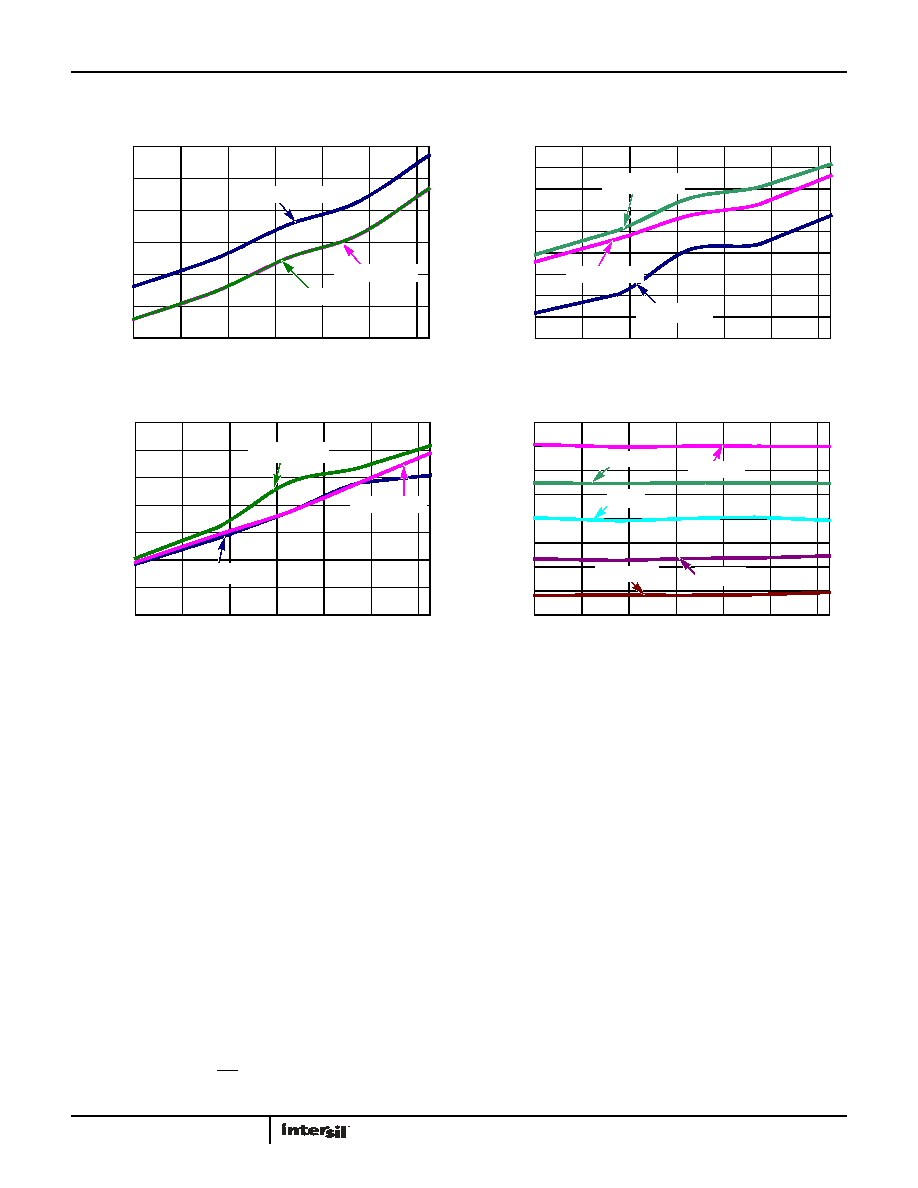
FIGURE 9. IDD vs TEMPERATURE, 3 DIFFERENT FOUT
FIGURE 10. IBAT WITH TSE = 1, BTSE = 1 vs TEMPERATURE
FIGURE 11. IDD WITH TSE = 1 vs TEMPERATURE
FIGURE 12. OSCILLATOR CHANGE vs TEMPERATURE AT DIFFERENT
AGING SETTINGS (IATR) (BETA SET FOR 1ppm STEPS)
Typical Performance Curves
Temperature is +25°C unless otherwise specified. (Continued)
2.5
3.0
3.5
4.0
4.5
5.0
5.5
-40
-20
0
204060
80
TEMPERATURE (°C)
SUP
P
LY
CURRENT
(A)
FOUT = 32kHz
FOUT = 64Hz
FOUT = 1Hz
20
30
40
50
60
70
80
90
100
110
-40
-20
0
20
406080
TEMPERATURE (°C)
I BA
T
(A)
VDD = 1.8V
VBAT = 5.5V
VDD = 3.0V
40
50
60
70
80
90
100
110
-40
-20
0
2040
6080
TEMPERATURE (°C)
I DD
(A)
VDD = 2.7V
VBAT = 5.5V
VDD = 3.3V
-80
-60
-40
-20
0
20
40
60
80
-40
-20
0
20406080
TEMPERATURE (°C)
FREQUE
N
C
Y
CHANGE
(ppm
)
62.5ppm
32ppm
-31ppm
-61.5ppm
0ppm
发布紧急采购,3分钟左右您将得到回复。
相关PDF资料
ISL12022MIBZ-T7A
IC RTC/CALENDAR TEMP SNSR 20SOIC
ISL12022MIBZR5421
IC RTC/CALENDAR TEMP SNSR 20SOIC
ISL12023IVZ
IC RTC/CLDR TEMP SNSR 14-TSSOP
ISL12024IRTCZ
IC RTC/CALENDER 64BIT 8-TDFN
ISL12024IVZ
IC RTC/CALENDAR EEPROM 8-TSSOP
ISL12025IVZ
IC RTC/CALENDAR EEPROM 8-TSSOP
ISL12026IBZ-T7A
IC RTC/CALENDAR EEPROM 8SOIC
ISL12027IV27AZ
IC RTC/CALENDAR EEPROM 8-TSSOP
相关代理商/技术参数
ISL12022MAIBZ-T
功能描述:实时时钟 REAL TIME CLK ENHANC CD ESD & MOISTURESIS RoHS:否 制造商:Microchip Technology 功能:Clock, Calendar. Alarm RTC 总线接口:I2C 日期格式:DW:DM:M:Y 时间格式:HH:MM:SS RTC 存储容量:64 B 电源电压-最大:5.5 V 电源电压-最小:1.8 V 最大工作温度:+ 85 C 最小工作温度: 安装风格:Through Hole 封装 / 箱体:PDIP-8 封装:Tube
ISL12022M-EVAL
制造商:Intersil Corporation 功能描述:Low Power RTC with Battery Backed SRAM, Integrated 5ppm Temperature Compensation, and Auto Daylight Saving
ISL12022MIBZ
功能描述:实时时钟 REAL TIME CLK & TEMP COMPENSATED CRYSTAL RoHS:否 制造商:Microchip Technology 功能:Clock, Calendar. Alarm RTC 总线接口:I2C 日期格式:DW:DM:M:Y 时间格式:HH:MM:SS RTC 存储容量:64 B 电源电压-最大:5.5 V 电源电压-最小:1.8 V 最大工作温度:+ 85 C 最小工作温度: 安装风格:Through Hole 封装 / 箱体:PDIP-8 封装:Tube
ISL12022MIBZ-EVAL
功能描述:电源管理IC开发工具 ISL12022MIBZ-EVAL DEMO BRD
RoHS:否 制造商:Maxim Integrated 产品:Evaluation Kits 类型:Battery Management 工具用于评估:MAX17710GB 输入电压: 输出电压:1.8 V
ISL12022MIBZR5421
功能描述:实时时钟 REAL TIME CLK W/MFK IMPROVED ESD AIR RoHS:否 制造商:Microchip Technology 功能:Clock, Calendar. Alarm RTC 总线接口:I2C 日期格式:DW:DM:M:Y 时间格式:HH:MM:SS RTC 存储容量:64 B 电源电压-最大:5.5 V 电源电压-最小:1.8 V 最大工作温度:+ 85 C 最小工作温度: 安装风格:Through Hole 封装 / 箱体:PDIP-8 封装:Tube
ISL12022MIBZ-T
功能描述:实时时钟 REAL TIME CLK & TEMP COMPENSATED CRYSTAL RoHS:否 制造商:Microchip Technology 功能:Clock, Calendar. Alarm RTC 总线接口:I2C 日期格式:DW:DM:M:Y 时间格式:HH:MM:SS RTC 存储容量:64 B 电源电压-最大:5.5 V 电源电压-最小:1.8 V 最大工作温度:+ 85 C 最小工作温度: 安装风格:Through Hole 封装 / 箱体:PDIP-8 封装:Tube
ISL12022MIBZ-T7A
功能描述:IC RTC/CALENDAR TEMP SNSR 20SOIC RoHS:否 类别:集成电路 (IC) >> 时钟/计时 - 实时时钟 系列:- 产品培训模块:Obsolescence Mitigation Program 标准包装:1 系列:- 类型:时钟/日历 特点:警报器,闰年,SRAM 存储容量:- 时间格式:HH:MM:SS(12/24 小时) 数据格式:YY-MM-DD-dd 接口:SPI 电源电压:2 V ~ 5.5 V 电压 - 电源,电池:- 工作温度:-40°C ~ 85°C 安装类型:表面贴装 封装/外壳:8-WDFN 裸露焊盘 供应商设备封装:8-TDFN EP 包装:管件
ISL12022MIBZ-TR5421
功能描述:实时时钟 REAL TIME CLK W/MFK IMPROVED ESD AIR RoHS:否 制造商:Microchip Technology 功能:Clock, Calendar. Alarm RTC 总线接口:I2C 日期格式:DW:DM:M:Y 时间格式:HH:MM:SS RTC 存储容量:64 B 电源电压-最大:5.5 V 电源电压-最小:1.8 V 最大工作温度:+ 85 C 最小工作温度: 安装风格:Through Hole 封装 / 箱体:PDIP-8 封装:Tube